The Hardest Part of a Raytracer Is Fitting It in Your Head
I've been interested in 3D rendering since I was a kid. I started programming at nine or ten years old, and I had no idea how people made such amazing graphics on a screen. It was a long time before I felt I could make one myself.
The motivation, when it finally came, was unexpected. Around 2022 I purchased a used Nikon Ti Eclipse research microscope from my employer at the time, AbCellera Biologics. I had been working with machine vision cameras for microscopy for a couple of years and had learned a great deal about how image sensors work. I got interested in computational imaging, particularly the work of Laura Waller's lab at UC Berkeley and the papers she published with Lei Tian on light field measurements using LED array microscopes. I wanted to replicate some of that work with my own microscope.
As I read their papers, I realized this was going to be a long learning journey. I needed a solid mental model for how light behaves, how images form, and how the physics of rendering works. So I decided to start by building a 3D renderer from scratch.
That was five years ago. The renderer is still growing.
Three Hundred Lines
I started with the "Ray Tracing in One Weekend" book series, adapting the C++ instructions to Go. My first renderer was a few hundred lines of code. It could render spheres. That's it.
What struck me immediately was how little code it takes to produce an image. Before I started, I expected I would need to write massive systems and implement dozens of subsystems before anything worked. Instead, a few hundred lines gave me colored spheres on a screen. I was generating images on my first day.
The other thing that surprised me was how iterative the process is. I never expected a renderer could be continuously evolved the way this one has been. I started with the crudest possible program and iterated on it thousands of times. Each iteration added something small. Over five years, the accumulation is dramatic. I kept a record of every image the renderer produced so I could see the project evolving in capabilities over time.
The Milestones
Finishing the Ray Tracing in One Weekend series was the first milestone. That's when I got hooked. From there I started reading other renderers' source code, particularly fogleman/pt, a path tracer written in pure Go. I was astonished at how fast and high quality his renders were compared to mine, and that drove intense curiosity to understand the tricks he used.
The second milestone was loading real 3D models. I implemented STL and OBJ importers from scratch and learned a lot about how those file formats work. The moment I realized I could download any model from the internet and render it in my own renderer was a genuine thrill. But at this point everything was still single-material objects. No textures.
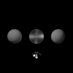
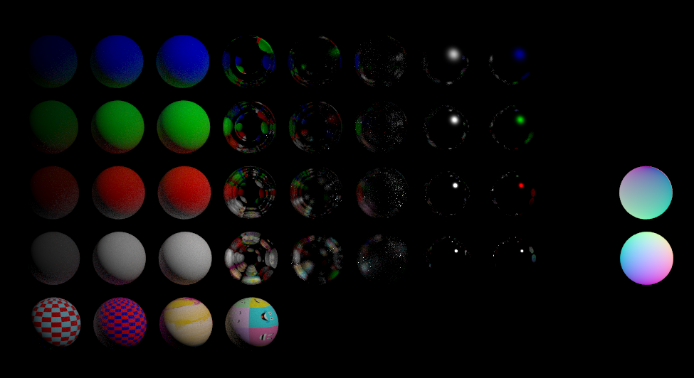
Materials came next. Metallic, dielectric, diffuse. They worked, but they looked wrong. The glass was too perfect. The metal was too clean. Real glass has flaws, reflections, and imperfections that everyone recognizes subconsciously. Real metal has complex microstructures that scatter light in subtle ways. Without those details, the renders had this unnatural, almost alien quality. This wasn't a code bug. The code was doing exactly what I told it to. The problem was that my mental model of how real materials interact with light was too simple.
That's what led me to "Physically Based Rendering: From Theory to Implementation." It was very challenging at first, but the improvements were dramatic. Physically based glass and metal transformed the quality of every render. The materials finally looked like things you could touch.
Lights
For a long time, my renderer used enormous area lights. The lighting model from Ray Tracing in One Weekend is simple, and I couldn't wrap my head around the math of point light sources. Area lights work, but they need a huge number of samples to render cleanly, and they limit the kinds of scenes you can build.
When I finally worked through the PBR book and understood point lighting, it was a revelation. The quality of the lighting went up immediately. I could place precise light sources in a scene and get the results I wanted. Even though the amount of code wasn't that much in the end, it was getting the math to fit in my head that was the real challenge. That's been the pattern with this whole project. The code is compact. The mental model is the hard part.
Scanning the Real World
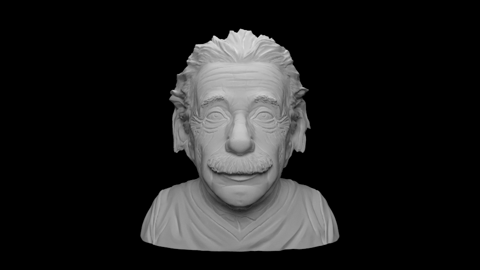
A later milestone was buying a Creality CR-Scan Otter, my first 3D scanner. It captures models and textures from real objects. This forced me to finally solve texture rendering, a longstanding limitation in my renderer that I had been putting off. The challenge was less about the code and more about understanding how texture coordinates map onto geometry, another concept I had to fit in my head before the implementation could follow. The payoff was worth it. The 3D scanner captures real-world lighting and surface appearance, and the resulting renders are some of the best I've done. There's an authenticity to scanned models that's hard to achieve any other way.
Another milestone was adding animated cameras. The renderer can now move a camera along a path while maintaining a constant gaze toward a target, which turned out to be essential for creating the demo animations I use to test new features.
Making It Fast
Once the mental model for rendering was in place, the remaining challenge was performance. But even here, most of the work was figuring out where the renderer was slow and why, not writing faster code. Three optimizations made the biggest difference.
Smarter sampling. The simple sampler from the PBR book evenly distributes ray samples across the image. Dark, empty regions get the same number of samples as complex surfaces with high variance. Switching to an adaptive sampler that allocates more effort to complex regions and less to simple ones was a huge win. There's a whole rabbit hole of sampler techniques, each with different tradeoffs and optical artifacts. Once I implemented it, I never looked back. Every competent renderer today uses something fancier than simple unbiased random sampling.
Profiling. Understanding where the renderer spends its time is what unlocks every other optimization. I designed data structures threaded through the key sections of the codebase to collect detailed rendering statistics. Without that data, I was guessing.
Parallel workers. Rendering is an embarrassingly parallel problem, but my first version was single-threaded. I added multiple workers that render patches of the image in parallel, with a scheduler dispatching work. One Go-specific pitfall nearly killed performance: using the global random number generator. Go's default RNG has a mutex, and with multiple workers hammering it, lock contention was enormous. I had to refactor so each worker had its own RNG. Performance jumped immediately.
Why It Matters
The renderer was never the goal. I wanted to understand optics well enough to do computational imaging, and the renderer was how I got there.
I studied engineering physics at UBC and took an optics class, but that's not the same as building a renderer. One of the great things about a raytracer is that if your conceptual model is wrong, reality smacks you right in the face. The render looks wrong, and you can see exactly how. When you finally get it right and a beautiful image appears, you know it.
Having a small, lean renderer that I knew deeply meant I could experiment with specialized scenarios that would be difficult in a large off-the-shelf renderer. I tested fluorescence, where one wavelength of light excites a material that then emits at other wavelengths. I modeled my 257-LED illuminator board, which I designed as a PCB for Fourier Ptychography based on the PhD work of Zachary F. Phillips. I later met Phillips and showed him my version of his illuminator. The renderer helped me test light field rendering and differential phase contrast methods.
The most valuable outcome is that I got over the initial barrier of having no mental model for image formation. Now that I understand it deeply, I feel like I can take on computational imaging problems that require rendering knowledge as a prerequisite.
Why Go, Why No Dependencies
I used Go because I was interested in learning the conceptual models, not in shipping a fast renderer. Correctness mattered more than performance. I also genuinely love writing Go. Coming from embedded and systems programming, I find it a joy to work with.
I used no external dependencies because I wanted to learn the entire stack. Vector math, material shaders, image format encoding, 3D model loaders, everything from scratch. If my goal was to bring something to market, I would use existing libraries. For learning, writing it all myself was the right choice. I know that because of how deeply I now understand every layer of the system.
The project is freely available at github.com/scottlawsonbc/raytrace.
You Should Build One
I encourage anyone to try building a renderer. It is surprisingly easy to get started. A few hundred lines of code gives you a program that generates images, and those images are rewarding in a way that's hard to get from other kinds of programming. Every time you run it, you get a picture. That feedback loop is addictive.
The reason it takes so little code is that the physics of light transport is compact to express. A few equations capture most of how light behaves.
It's a project that is easy to start and difficult to master. I started with spheres and I'm still adding features five years later. Each improvement sends me down a rabbit hole of curiosity that teaches me something I didn't expect to learn.
What surprised me most is how the renderer grew alongside my understanding. I never sat down and improved the renderer directly. I'd learn something about how light works, and the renderer would get better as a consequence. After five years of that, the renderer is less a product I built and more a record of everything I learned.
Once I had a working mental model for light transport, I started seeing it everywhere. Caustics in pools, imperfections in glass, the way metal scatters sunlight instead of reflecting it cleanly. I'm still working on the renderer. I expect I will be for a long time.